
tl;dr
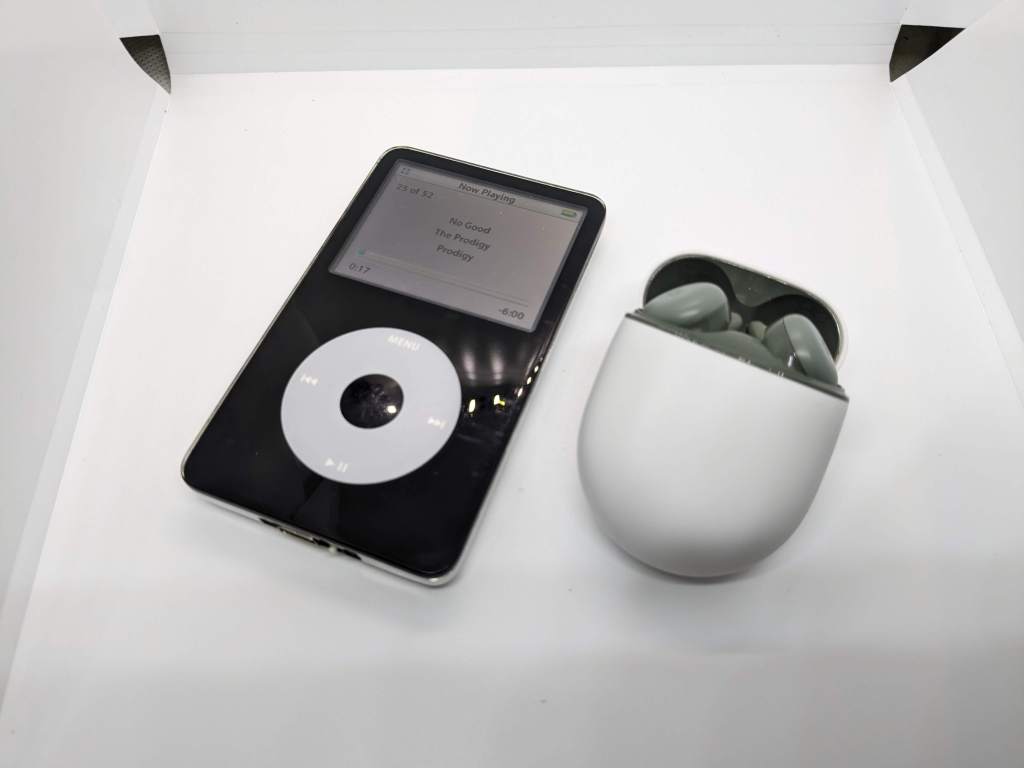
I started to using a iPod again, This go me wanting to add a few modern touches. My first thought was Bluetooth then next was USB C charging and data but didn’t know if it was possible. I was used to adding USB C power to things but never a data connection. Join me below to see how I pulled these hacks off.
Hardware – SSD

This is probably the easiest mod/hack that you can do to your iPod, Also it lets you add a bigger battery to boot. I ordered the 128gb version, It comes with a new back shell which is nice. All you need to do is crack open your iPod and remove the old battery and hard drive then slip in the SSD and larger battery. I covered my SSD in kapton tape because I was going to be adding more stuff into the now freed up space space.
Hardware – Bluetooth
I’ve dealt with Bluetooth transmitters in the past but realized that modern Bluetooth headphones use Bluetooth 5.0 so I had to look for a new transmitter, I started looking for a battery powered module but they all seamed too big and bulky. Then I found the perfect dongle, Think its meant to plug into the USB port on a TV then you attach the 3.5mm headphone lead to the TV and transmit to your headphones, It does transmit and receive but its set to transmit by default which makes our life easier.
I started by connecting the dongle to an external power source and then the 3.5mm jack into the iPod, It connected to my pixel buds so that was a good start since they are Bluetooth 5.0. Next I started to tear down the shell of the dongle, There wasn’t much to them and I knew I would be able to fit them in the iPod shell.


I was planning to cut down the USB contacts, remove the 3.5mm headphone jack and the button since we wont be needing it. I planed to just hard wire the 3.5mm jack to the iPods jack internally. This made it a really nice small package. Before removing the 3.5mm headphone jack I plugged the lead into the dongle and the iPod used my multi meter to see which part connected to each other, this made it really easy to solder it up later. I had to remove the 3.5mm jack from the back of the iPod shell to get access to solder it. Below shows which solder points need to be soldered together. I used thin 0.25mm/30AWG solid core enamel wire because of the tight space.

Also you might want to cut down the USB part of the dongle, As shown below the VCC (5v) is on the right of the USB port and GND is on the left side. Once you remove the 3.5mm headphone jack you will need to connect the top pad on the right to the bottom left pad otherwise you want get any audio out of your dongle as shown below.


For power I tapped into the capacitor next to the hard drive connector as marked below. There was another problem with this Bluetooth dongle, It constantly consumed power and would drain the iPod battery even when not in use. I needed away to turn this dongle on and off when not in use. This is where I found the smallest switches I could find and add it to the USB C port board. Scroll down to see the details of the USB C port board.

Hardware – USB C power and data
Ive added USB C charging to quite a few things over the years but I have never had to add data too. I normally use a 6 pin USB C connector but I needed to find a USB 3.1 connector, Luckily I found that the lipo charge board I had been messing around with had a 12 pin USB C connector on it that would let you do charging and data. I had to find the footprint in kicad and work out the D+ and D- pins for this connector.
We are going to need to strip the iPod down to the bare PCB to install the USB C replacement PCB. This really isn’t for the faint of heart and requires you to have good soldering skills.
After tearing down your iPod the first thing we need to do is to remove the 30 pin connector. I found that if you use a solder sucker to remove as much solder from the 4 anchor posts then use hot air from the bottom of the board because we don’t want to damage the HDD connector. Once the 30 pin connector comes free we need to make sure to remove all the solder off the connector pads so the replacement PCB will lay flat.
The next job is to line up the PCB with the edge of the iPod PCB and equally over the anchor points, When your happy with the placement tack down one side of the PCB and then check it against the magnesium chassis, If it all looks good then solder down the other side. Start with the GND (black) solder point far right of the USB C PCB, Run your wire over to the cap. Moving onto VCC (red) the far left on the USB C PCB run a wire to the 8th pad from the left of the 30 pin connector. Next we are going to do D- (white) second from the left on the USB C PCB this ones going to the top side of the labeled in white. Make sure the wire sits on top of the PCB otherwise it will get in the way of the hard drive ribbon cable

Hardware – 3D printed cover

Because we have removed the old 30 pin connector there will be a big gap in the shell, I have designed a 3d printed part that replaces the plastic port surround in the back shell. I made 2 different versions one with just the USB C port hole (ipod_usb_c5.stl) and another with a hole for the switch as well as the USB C port (ipod_usb_c4.stl). I’ve uploaded them to my Github below, Best way to print them is with the screw holes flat on the bed and use support.
Files
https://github.com/facelesstech/ipod_usb_c_charge_and_sync
Video

Leave a comment