tl;dr
I’ve always liked fidget toys but I always thought they were missing something, This is why I decided to make some fidget toys but with electronics in them. I raided my parts bin and found a nice clicky encoder and set about hacking, Join me below to see what I came up with.
Hardware
- Arduino pro micro USB C
- WS2812 16 LED ring
- Custom tp4056 charge/boost board
- E-cig lipo battery 13400 550mAh
- Latching switch 7mm x 7mm
- Rotary encoder push button
- 2.5m 6mm hex bolts x4
Custom TP4056 10A45
This was the first project to show case this custom board I had been working on. I’ve wrote a blog post with all the details if you want to find out more about it and build your own.
Encoder wiring and code

I knew I had ordered some encoders that were nice and clicky in the past so I dug them out of my parts bin. I had never used these before so I went looking for a library to use with my Arduino. I tried so many different library but some didn’t quite count the rotations right but I did find one that worked just as I needed. I did try and write some code to test out my setup but then I turned to chatGPT and it was a disaster, It did give me some code but it wouldn’t compile, When I tried telling chatGPT that it wasn’t working a few times it decided to switch library’s which didn’t work with my encoder. After looking over the library examples I did get it working and did give me a good base to work from but I don’t think it saved me any time or effort.
Its quite easy to hook up even if you use the bare encoder to an Arduino as seen in the image above.
Encoder library – https://github.com/M-Reimer/EncoderStepCounter
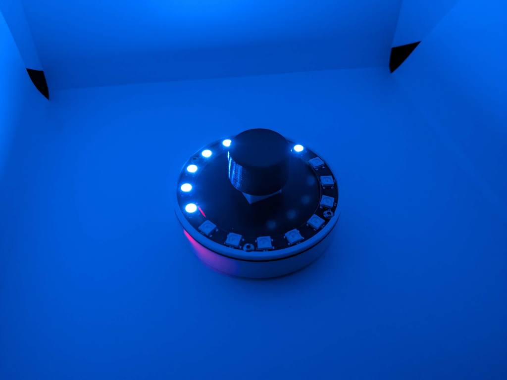
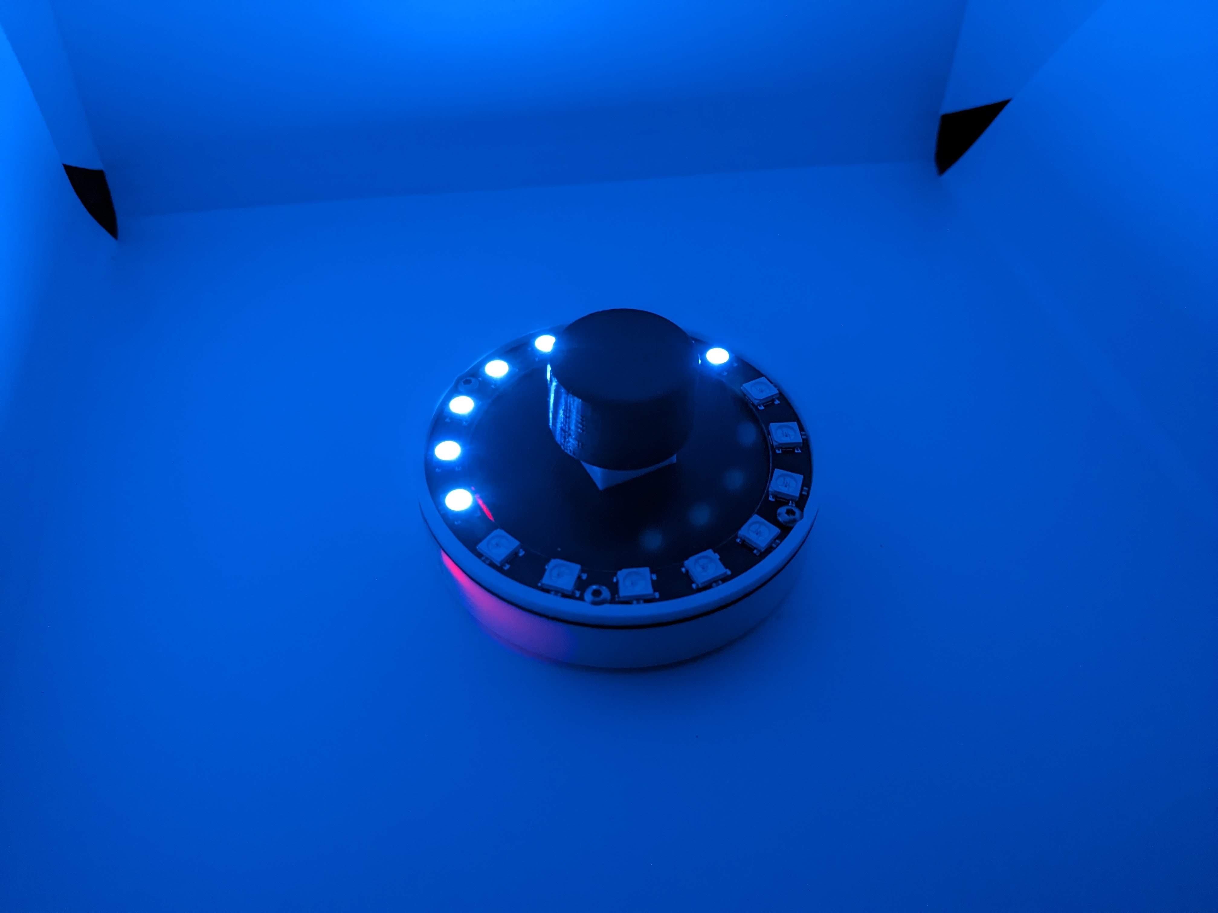
WS2812 ring of light
The main star of the show was the WS2812 light ring, I picked a 16 LED light ring because it was just the right size to fit the Arduino battery and charger all within its diameter. As with all my ws2812 projects I’m using the FastLED library because its easy to use and there are loads of examples out there. I hooked the date pin up to Arduino pin 6 for this build.
3D Printed Encoder

The size of enclosure was determined by the size of the WS2812 LED light ring, lucky I could fit the Arduino pro micro and the tp4056 + 10A45 board end to end with the USB C ports sticking out each end. I was using a recycled lipo out of a “disposable” vape which I had to add a protection PCB but since it was a cylinder shape in the rectangle hole there was space for it. I used a latching switch of the power sticking out the side. I was struggling to find a clever way to fix it together, I noticed that the ws2812 ring has four 2.5mm holes in it so I decided to have that on top then made a lid of the bottom that would be sandwiched between the ring and bottom this would also house the encoder. This was a massive pain to put together but worked for this one off build. I embossed “USB” in the Arduino USB C port side and embossed a battery icon in the tp4056 USB C port so I wouldn’t get the 2 ports mixed up when charging.
Files
3D print files – https://www.printables.com/model/649291-fidget-encoder
Arduino code – https://github.com/facelesstech/encoder_fidget
TP4056 + 10A45 files – https://github.com/facelesstech/tp4056-10A45
Video

Leave a comment