
tl;dr
I got the chance to grab a circuit shield kit, I jumped at the chance because I always miss the pre-orders. I didn’t really know what I was getting myself into because it was more involved then I first thought. As usual I’ve put my own spin on this build. Join me below to see how I pulled it off.
Hardware
- Circuit shield PCB
- Circuit shield Screen
- Circuit shield button cables
- Circuit shield Speaker
- CM3 Lite
- 4000 Mah lipo battery (505080)
- Shoulder buttons
- Shoulder buttons PCB
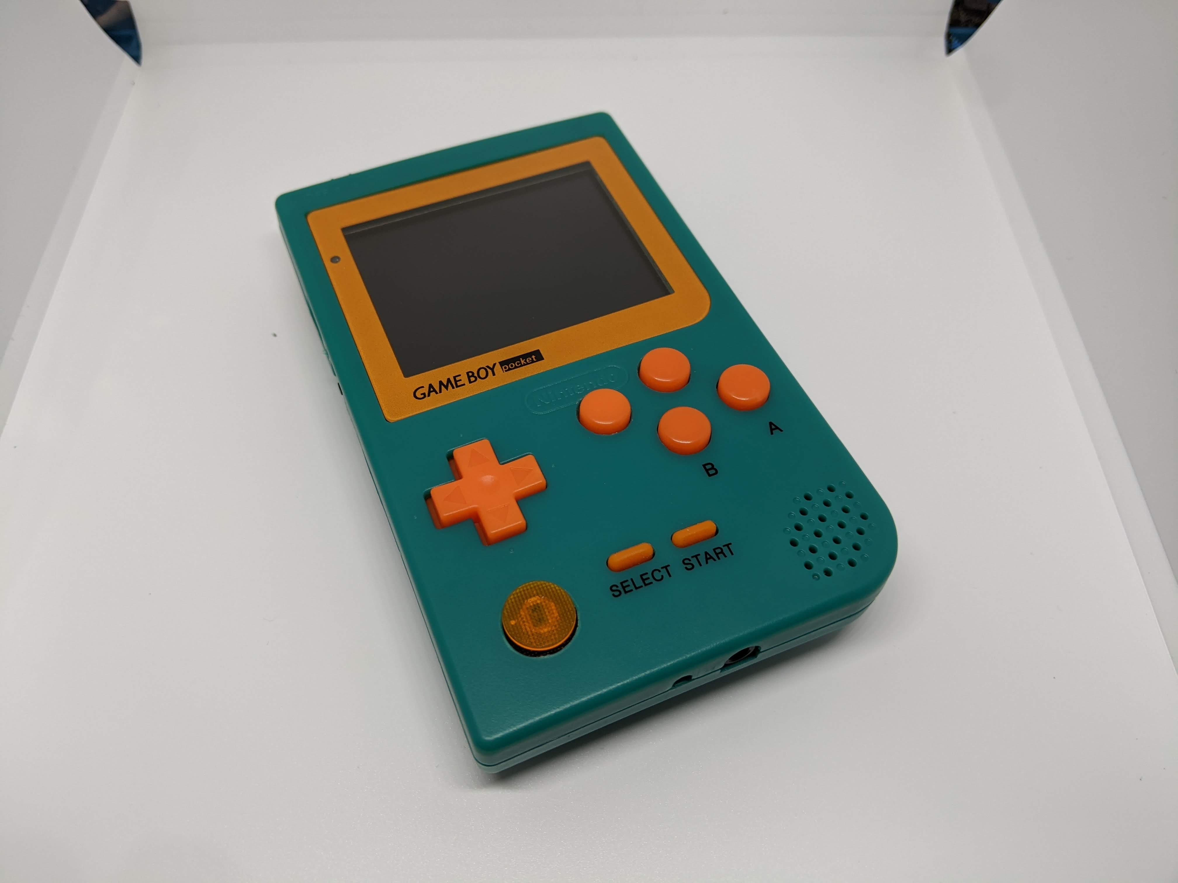
- Gameboy pocket shell
- 3D printed parts
- My own 3d printed parts
- Custom glass gameboy pocket lens
- PSP thumb stick
Shell cutting
This is the best place to start, Its the hardest part of build so lets get it out of the way.
Screen
Start by cutting the front screen surround flush with the shell, Use a craft knife and a small file. I’m using 3d printed files I found HERE. You will need to print the “Ant’s Screen Bracket.stl” file first, I had to file it down to fit the screen in but it lines the screen up nicely.
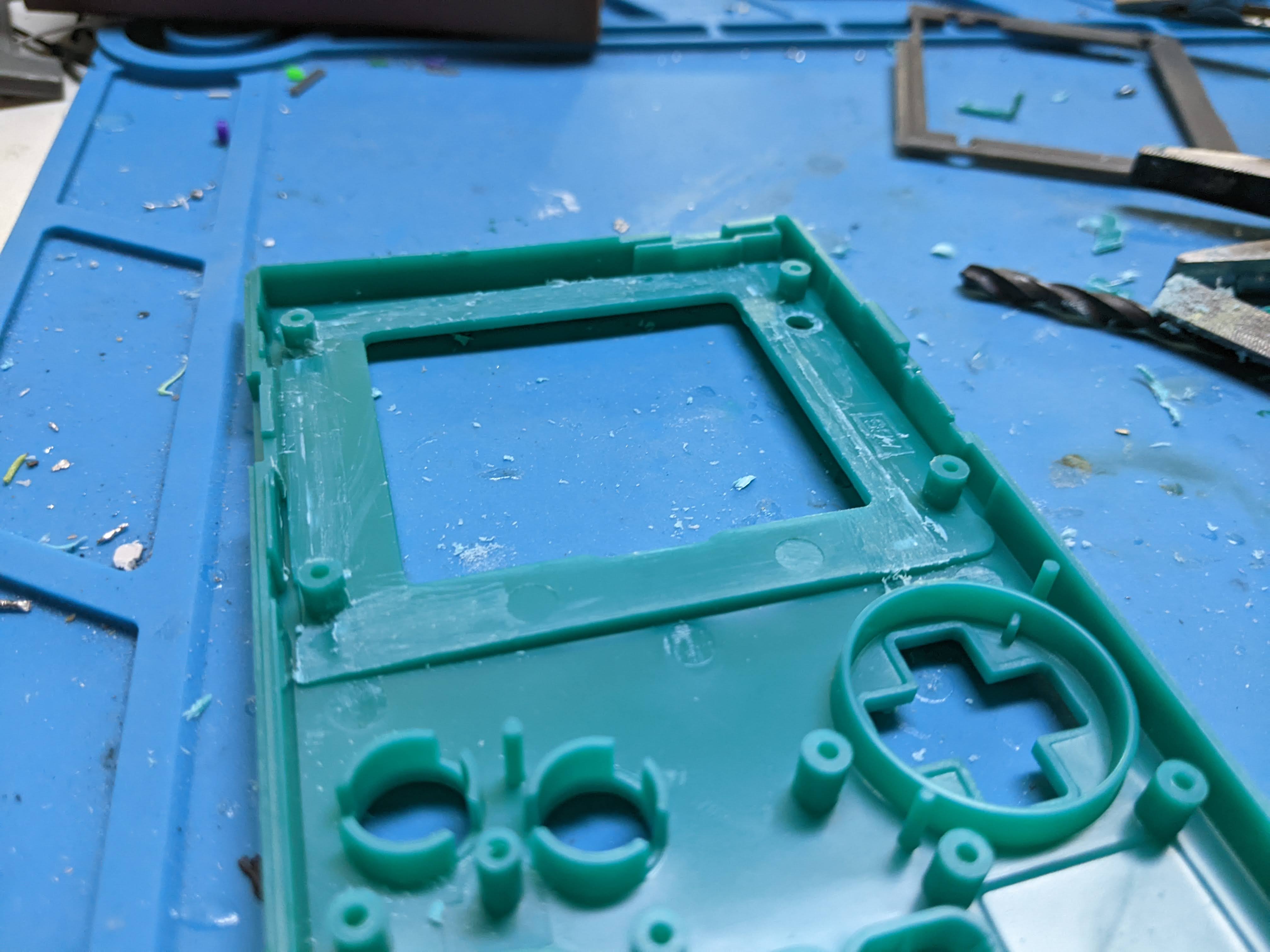
Once you are happy with the fitment of the screen you will notice that the shell covers part of the screen. What I normally do is mark where you want to cut (don’t worry about taking too much off because the screen lens will cover it) The screen lens was ordered from bluish squirrel, They were so helpful in making sure I was getting exactly what I needed.

then use a craft knife and score along the line you marked, Next cut down to the scorned line with a jr hacksaw blade. Grab the plastic and rock it back and forth till it breaks off
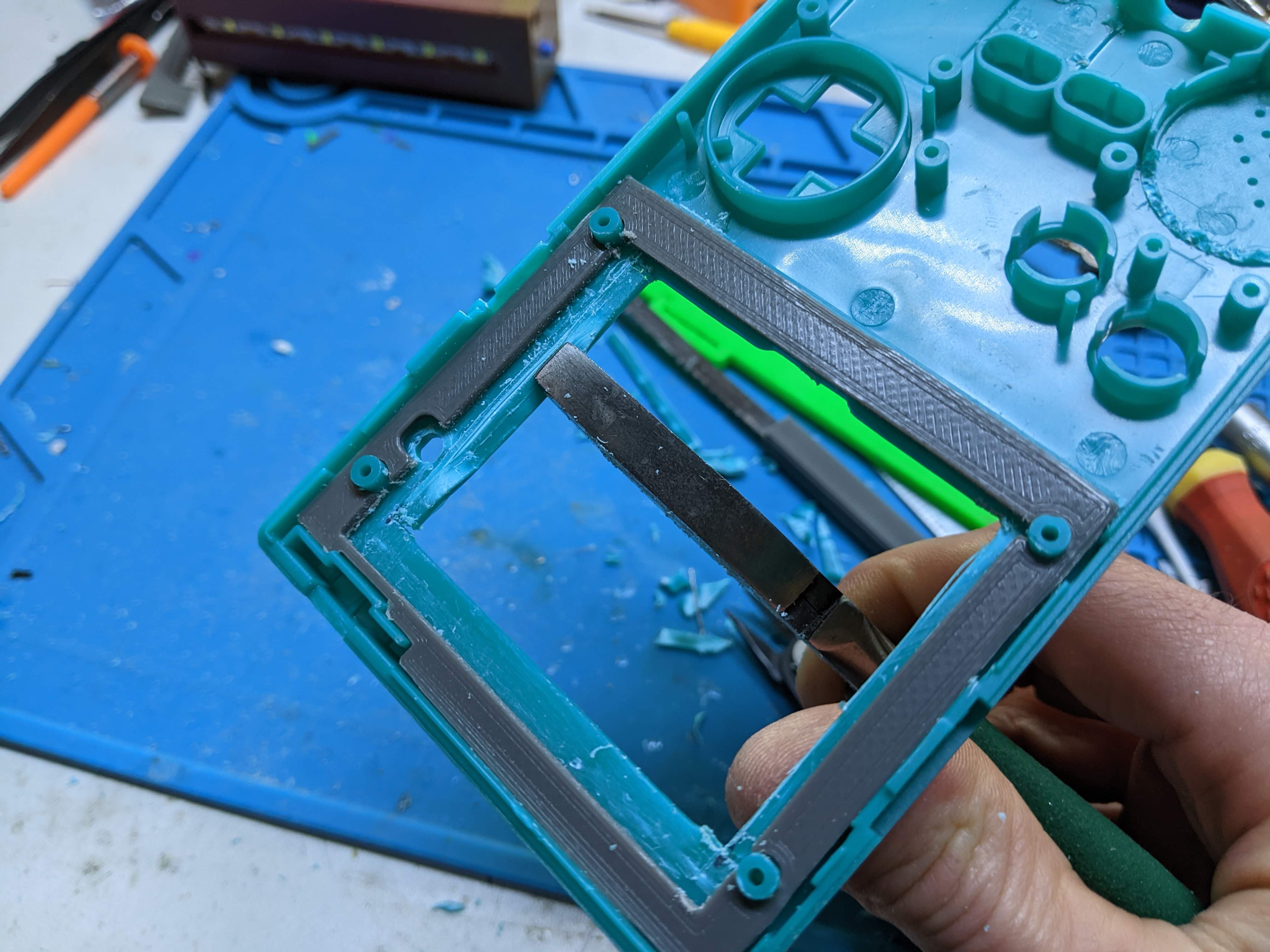
Pop the screen back in and see if all the screen is visible, If so lets move on to the next part.

Extra buttons X & Y
As you all know the gameboy pocket only came with A and B buttons, We want to add X and Y buttons for this build. I found a drill guide to help with the drilling of the holes HERE you will need the “Ant’s Joystick Drill Template 3mm.stl” The pilot hole size is 3mm and will need to be opened it to 7mm. To support the new buttons we need button wells, I originally tried the supplied button well files “Ant’s Button Well.stl” but I found that they didn’t work for me. I ended up reverse engineering the button well file and made it work for my build, My files are available HERE. I also had to cut the button membrane to fit next to the A and B buttons but its not much.
Speaker
The speaker is quite simple, You are supplied with the speaker and the speak wire which is socketed on the board. The shell does need to be trimmed so it can fit, Some flush cutters and a knife make short work of that. Also while we are cutting stuff in this area we need to cut a few posts around the headphone jack and DC jack shown below.

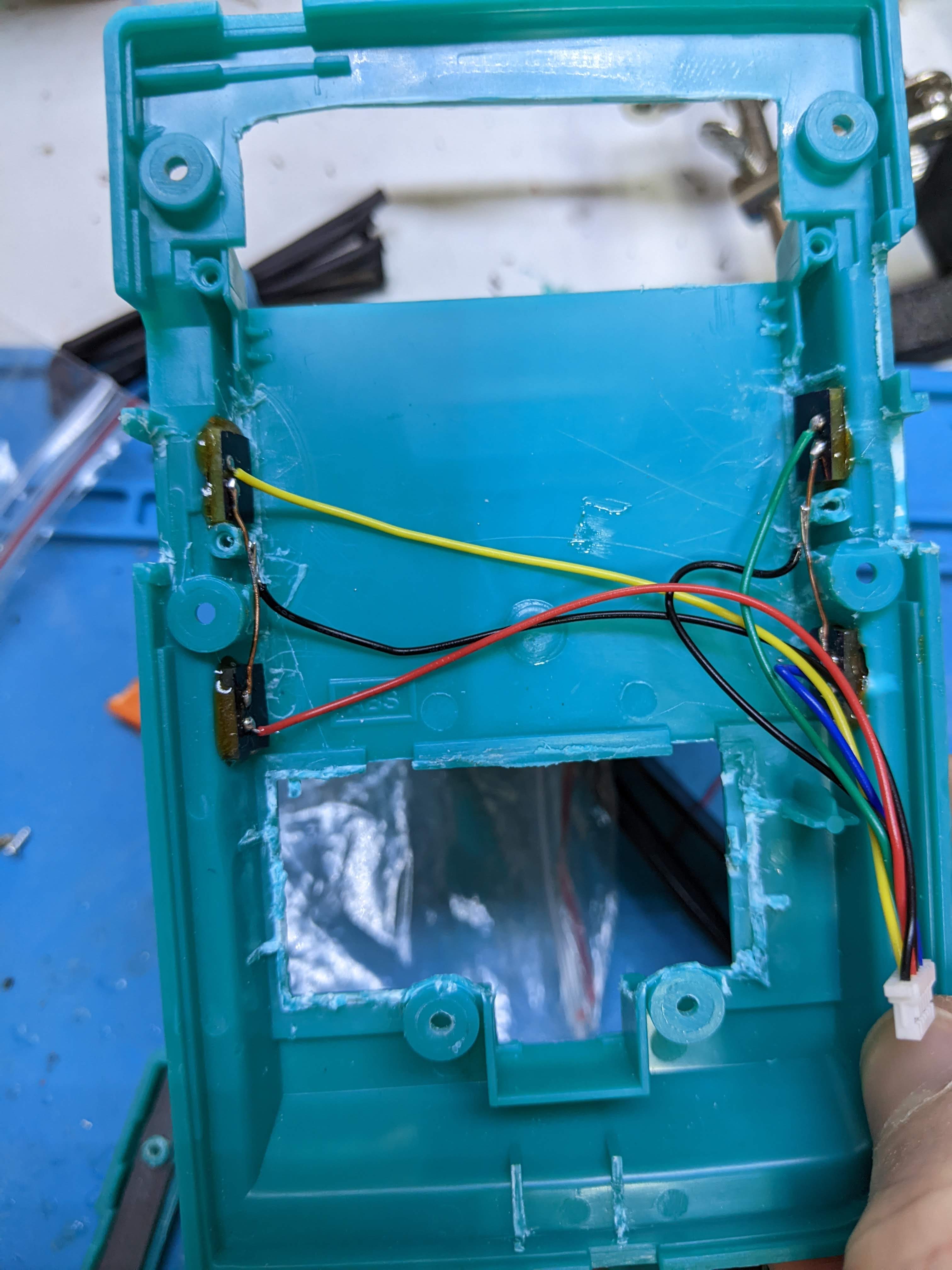
Shoulder buttons

This part of the build was quite vague when doing the research of this build, As far as I could tell was that most people were using clicky buttons but I hate clicky buttons so I had to get my thinking cap on. I found some small soft touch buttons that I used on a old controller project HERE, I had also made some PCB’s that I was using to turn them into 90 degree buttons, These would be perfect and would let me mount in into the shell. I just eye balled the drilling of the holes, Just making sure that they would fit in the shell and be symmetrical. I used some 2 part epoxy to glue them in place and then wired up the supplied shoulder button wire.
Joystick
There are 2 options for the joystick you can ether go with a psp sliding thumb stick or a ps vita one. I went with the psp one because I quite like it and its very low profile compared to the vita one. Solder the 4 psp pads to the board. There is a drill jig of drilling the hole in the right place HERE, It will need to be opened up to 12mm. You might have fitment issues with the shell so you might need to files down the inside front shell until you get good movement on the stick.
Back shell cuts
Since we are done with the front shell cuts lets start on the back shell. First you will need to remove the battery bay completely except for the screw holes because we will be using them later, Its a kinda trial and error sort of process where you will need to keep trying your board in the shell until it fits, I think THIS video is also good to watch.

You will need to remove some plastic around the ports, As always just go slow and keep trying the board in the shell to see if it fits. I found the HDMI mini port to be difficult to pull off.
Part of the cart slot will need to be removed, I used the same method as with the screen, Score a line with a knife and cut down to it with a hacksaw blade then rock it back and forth till it comes off. Also the cart runners will need to be removed too to make room of the massive 4000 mah battery. Because we have removed part of the shell around the cart slot we need to cover it up and the battery, I designed this fake cart cover around the NES cart, You will just need to hot glue it in place. It even has vent holes to keep your build running cool.

HDMI out and safe shutdown
This are the best feature of this build. The HDMI out is accessed in the retropie menu off the main screen, There is an option call “Single reboot to HDMI out” what this does is reboot the system so that the screen is piped over HDMI so you can plug it into your tv, Once you have finished you can power it down then the next time it will boot to the screen. The other feature I really like is the safe shutdown, You can hit the power button and it will tell the pi to power down safely without your fiddling with menus and the like.
Links
SD Card image – https://github.com/kiteretro/Circuit-Shield
3D print files – https://sudomod.com/forum/viewtopic.php?t=10997
A good video and some more info from Wermy – https://sudomod.com/circuit-shield-and-march-update/
Files
All the 3d printed and PCB files that I’ve designed – https://github.com/facelesstech/circuit_shield
Video

Leave a comment