
tl;dr
Come with me on a journey into making a pigrrl 2 kit. This isn’t absolute guide more of what I’ve learned and any info to help other people on the same journey
Intro
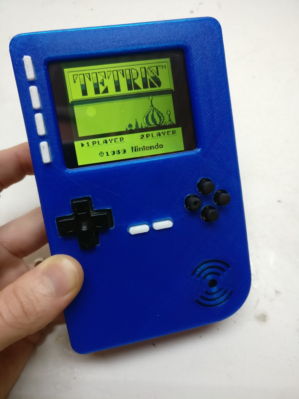
The last real video game I played was time splitter 2 on the gamecube, Since then I kinda fallen out of love with games. I really like the older games like the NES, SNES, N64 and the Gameboy games too. I wanted a way that I could easily play my old favorites and to be portable to boot. I started looking at converting an original gameboy (Gameboy Zero) but I hated how everything was hot glued down and messy so after a bit more searching I found the Pigrrl 2 project.
After a bit of searching I found quite a few mods that could be done to the pigrrl 2. I thought I would see if I could find any further mods and tie all the other mods together into this blog post. Without further ado let’s get into what I’ve found
Mods
As I was looking around and researching the pigrrl I wanted to see if there were any improvement people had made or any that I could add.
Buttons
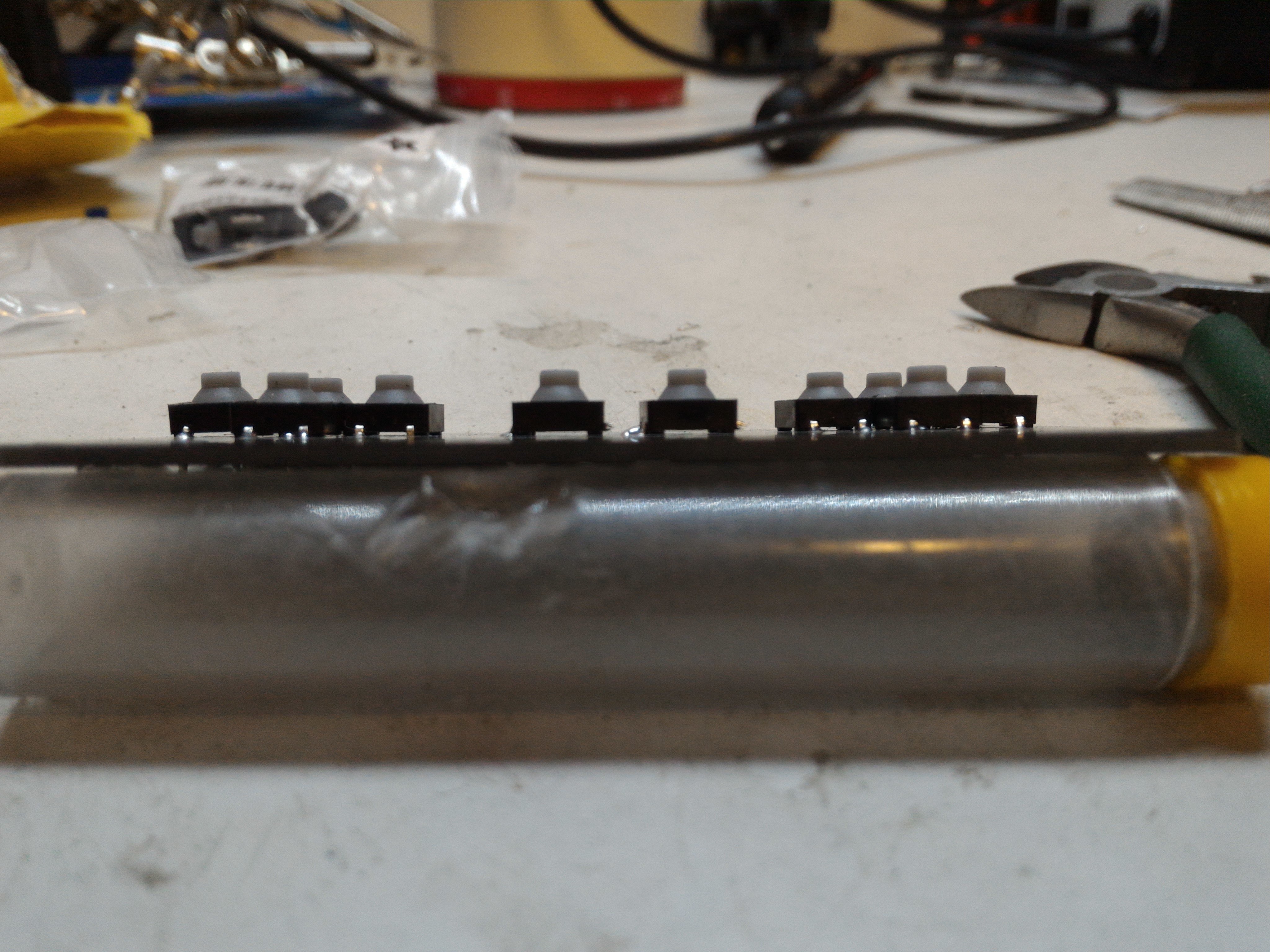
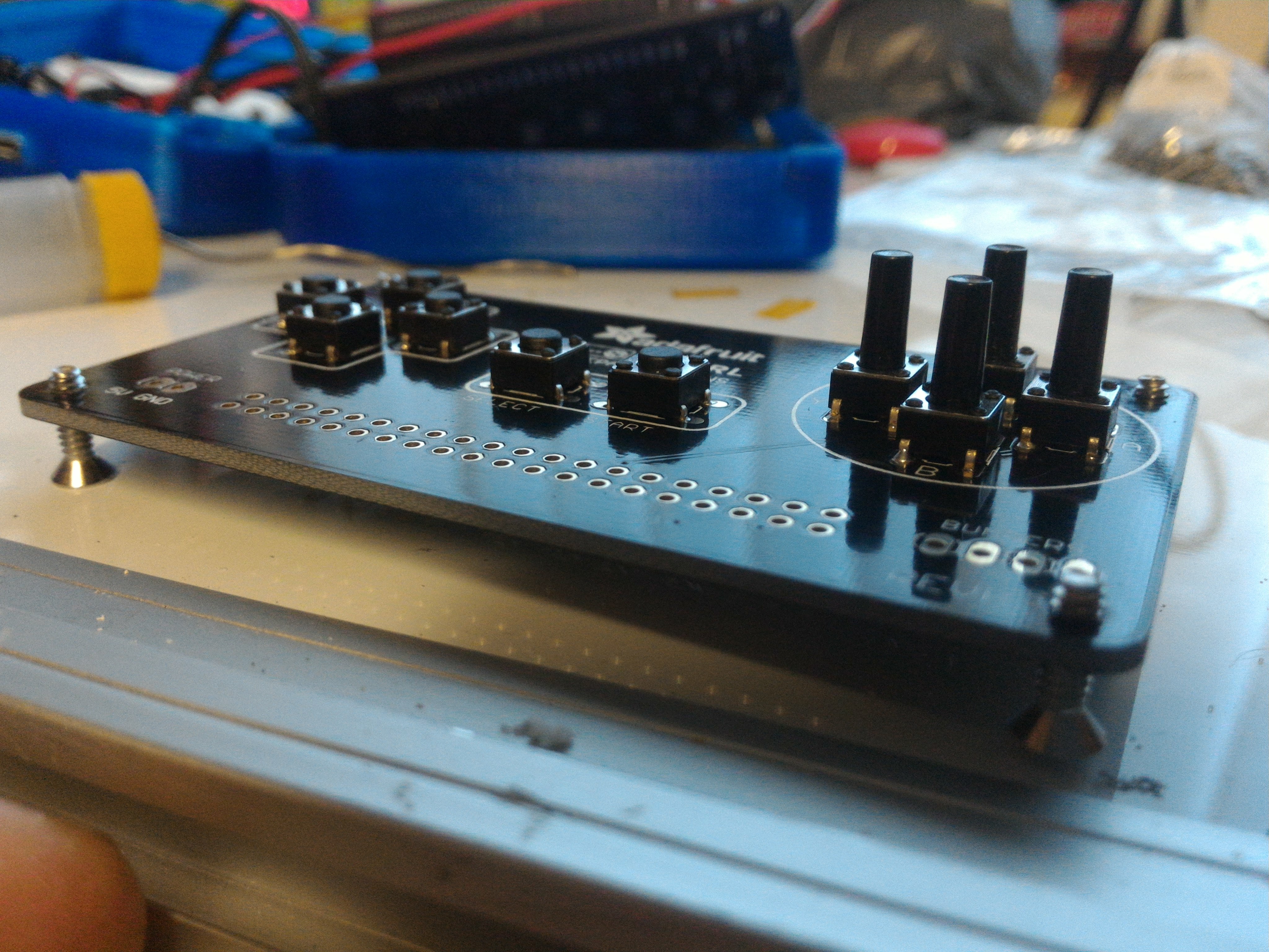
This was what almost made me not do this project, I was looking on YouTube at a few videos of the performance of the Rpi3 and I noticed that the buttons they use were the horrible cheap clicky push buttons. After a bit more research I found that you can use elastomer (Think gamepad membrane) soft tactile buttons. The only problem with these button is their 6mm x 8mm instead of the clicky 6mm x 6mm buttons. Here is the problem the pigrrl button PCB is made for the 6mm x 6mm buttons, On the adafruit website they don’t really tell you what to do other than cram them onto the board like in the picture below.
 
I even messaged a eBay seller that sells the fully assembled pigrrl 2 kit because in the listing they mentioned they use the soft buttons, but they only said they buy 6mm x 7mm from china in bulk. This didn’t really help me.
I remembered back to when I used to use the 6mm x 6mm buttons in my PCB designs and how you would only need to hook up 2 of the button pins, I started probing around the pigrrl buttons PCB and found that they had done the same. I can’t believe that no one else had come to this conclusion. All you need to do is cut off the unused pins off the larger soft buttons and solder them down. There is still a problem fitting the buttons on the PCB because the button housing is bigger so had to file down the corners to get them to fit flat.

After going thought all the trouble of getting the membrane buttons getting them to fit on the PCB they didn’t work out. The problem about the membrane buttons is that it’s too easy to accidentally press the wrong direction on the D-pad. This could be to do with the fact that I was using PLA D-pad and not the ninjaflex, This is because the Ebay seller cheapened out on me.
I also hated that because of the 3D printing layers of the D-pad that it would snag on the case, I tried to sand the D-pad down but it was impossible. At this point I had decided to go back to using the normal clicky buttons and pulled a D-pad out of the old broken NES controller.
For the buttons I did away with the 3D printed part and used long nose (8mm) clicky buttons. These were long enough to come thought the case, The problem with these buttons is that they are uncomfortable. The buttons are 3mm diameter so I found some RC controller aerial rubber ends that fit so there quite comfortable now.
For the shoulder buttons I stuck with the membrane one since they didn’t suffer from the accidental presses like the D-pad did.
The start and select buttons I used the click one like the ones in the D-pad
LED’s
I seen that someone had come up with a great mod that would tell you when the battery was getting low, It uses a transistor and a resistor you can find that mod HERE. I was going to use this in my build and even went as far as to get a PCB made for it HERE. Lucky for us the PowerBoost 1000 Charger board as a low battery LED on it, All I’ve done it to extend the LED out to a 3mm led and drilled a hole in the case and used a LED holder to keep it secure.

I wanted to also extend the ACT led off the pi’s board, The reason for this is that when you shutdown the pi you have to wait for the ACT LED to blink on/off 10 time before its safe to cut the power. Yes you could just wait 30 after shutdown before cutting the power but ive seen it sometimes really take its time to shut down so now I don’t have to worry about that. I also drilled a hole in the case and used a 3mm LED with a LED holder.

Power switch
I really didn’t like the way that they did the power switch, In the adafruit guild they just pushed a switch into the hole in the case but I wanted to have a more secure solution. I had to file the hole to be a little bigger and add some holes for the screws. The way I made the holes for the screws is by heating up a needle and pushing it thought the case, The reason for this is the screws were very small and I didn’t have a drill but small enough for them.
Button config
The pigrrl controller PCB will need to be configured before you can use it as a controller, To start the setup we need to copy and paste these lines into to your terminal
cd
curl -O https://raw.githubusercontent.com/adafruit/Raspberry-Pi-Installer-Scripts/master/retrogame.sh
sudo bash retrogame.sh
Choose pigrrl 2 option then reboot. If you haven’t added a controller yet you will presented with the configure input screen. If you have already setup a controller you will need to press start and select the configure input option then just press the buttons you have (To skip buttons just hold down an already set button and it will skip it).
Hotkeys
You may notice like i did there wasn’t a hotkey for saving with the pigrrl buttons, normally on a controller you press the hotkey (select) then L shoulder button to load and R shoulder button to save. You will need to edit a file to enable this.
The file you need to edit is /opt/retropie/configs/all/retroarch.cfg open this file with your favour text editor.
To set the hotkey you will first need to search the file for
input_player1_select
make a note of what key has been set, Next you need to search for
input_enable_hotkey_btn
uncomment this line by deleting the # at the start of the line then add in what button
input_player1_select
was set to.
To set the save buttons. First search for
input_player1_l
make a note of what key has been set, Next you need to search for
input_save_state
uncomment this line by deleting the # at the start of the line then add the key that was set at
input_player1_l
To set the load buttons. First search for
input_player1_r
make a note of what key has been set, Next you need to search for
input_load_state
uncomment this line by deleting the # at the start of the line then add the key that was set at
input_player1_r
By default the space key which is what we are using as a hotkey will when pressed speed up the emulator. So when you press it to save or load the emu will speed up until pressed again. To stop this you will have to go into /opt/retropie/configs/all/retroarch.cfg file again, Search for
input_hold_fast_forward =
you will need to uncomment it by deleting the # in front of that line and add ‘x’ after the = like so
input_hold_fast_forward = x
Audio hotkeys
If your like me and wish there was a volume nob for the pigrrl 2, this is the next best thing. Again we are going to be going into /opt/retropie/configs/all/retroarch.cfg file. You will need to search for
input_volume_up =
uncomment the line by deleting the # in front then adding
num1
after the = like so
input_volume_up = num1
Next search for
input_volume_down =
uncomment it and add
escape
after the = like so
input_volume_down = escape
This will let you turn the volume up and down using the bottom screen button and the second from bottom screen button.
If you want a mute button you will again need to open /opt/retropie/configs/all/retroarch.cfg file and search for
input_audio_mute =
uncomment it by deleting the # in front of it, add
num2
after the = like so
input_audio_mute = num2
This will turn the second from top screen button into your mute button.
Theme
If like me you struggle to read the text on the default theme that comes on retropie, I have found a theme that will fix it.
cd etc/emulationstation/themes
sudo git clone https://github.com/smartroad/es_theme_pigrrl.git
Once you have cloned the repo you will need to apply the theme, press start to pull up main menu then scoll down to UI settings then change the theme set to ES_THEME_PIGRRL.
Headless setup
So I had a thought about what you would do if you had to re-image your sd card with a clean install of retropie. The way you might set up a fresh install would be to connect your rpi up to a screen and use a keyboard and mouse, with your rpi in the pigrrl 2 case you can’t connect up a screen because you can’t get to your HDMI port.
I found a way round this, First task is to get your rpi on the network so you can SSH in. To get your rpi online using retropie you will need to edit a this file /retropie/etc/wpa_supplicant/wpa_supplicant.conf. You will need to add below to the end of the file.
network={
  ssid="your-network-ssid-name"
  psk="your-network-password"
}
Dont forget to change the ssid and psk to be the same as your network you want to connect to. Save the file then pop the sd card into your pigrrl 2. It will need to expand the file system and reboot but you wont see this because the screen isn’t working yet so just give it a minute before SSH in. Once you have SSH’d in you will need to go to the adafruit site and grab the install commands for the screen and gamepad HERE, I will put them below if your lazy ;).
Screens install commands, Don’t reboot until you have installed the joypad commands
cd
curl -O https://raw.githubusercontent.com/adafruit/Raspberry-Pi-Installer-Scripts/master/pitft-fbcp.sh
sudo bash pitft-fbcp.sh
Joypad install commands then reboot
cd
curl -O https://raw.githubusercontent.com/adafruit/Raspberry-Pi-Installer-Scripts/master/retrogame.sh
sudo bash retrogame.sh
Once it come back from the reboot you should be presented with a working screen and the config input screen to set up your controller. That’s it your back up and running, Just copy your roms and configure your hotkeys like I showed you in the buttons section of this blog.
Audio
This is where I had heard the most complaints about people getting horrible interference from the power cables and battery. I found that if you put the battery up behind the screen and ribbon cable I didn’t get any of the screeching noise other were getting. I found this forum post about changing the refresh rate of the screen helped to stop the screeching. Search in the /boot/config.txt file for
dtoverlay=pitft22,rotate=270,speed=80000000,fps=60
and change the speed from 8000000 to 4800000 like so
dtoverlay=pitft22,rotate=270,speed=48000000,fps=60
Its been a long-standing complaint with raspberry pi in general that you have a hissing sound when you plug-in headphones or speaker. I found that if you add
disable_audio_dither=1
to /boot/config.txt it goes away.
Pro tips
Pi cable
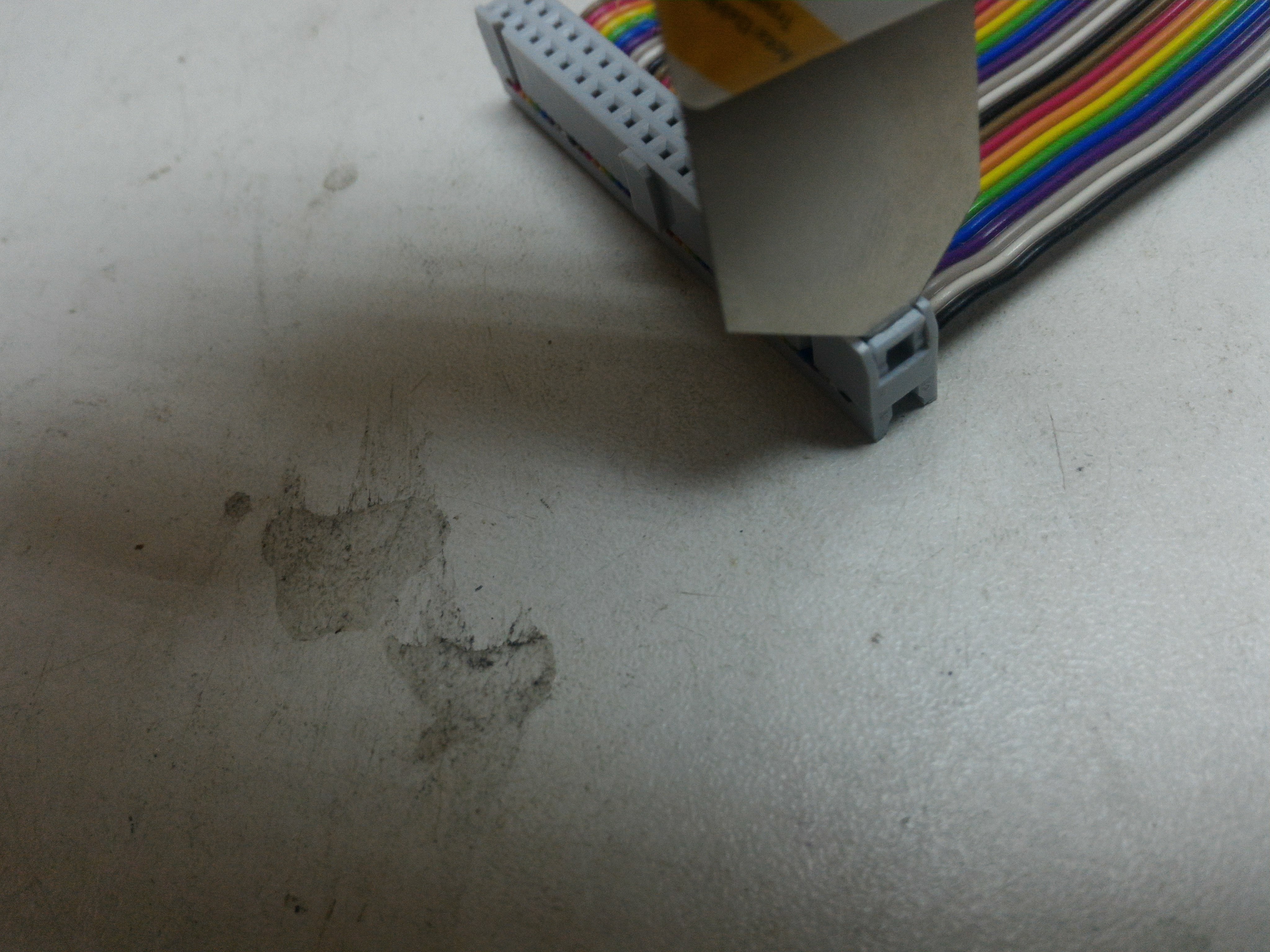
So this is something I thought would be easy to do, and the adafruit guild made it look that way too. The most annoying thing about the Pi cable is that you can’t use a standard 40 pin IDE cable you find in your computer. This is because one of the pins is blanked off on these cables. If you’re looking of one its best to search for a “Raspberry pi GPIO cable”.
Once you have gotten your cable you then need to see if your cable comes double clipped like mine did in the picture below

If your cable does come double clipped just use and old credit card to remove it by flicking out the clips on both sides, You don’t need this clip so you can bin it.
This next clip you need to remove you need to be really careful with, If you break the clips off of these you will have a hard time getting it back together like I did. The best way to remove them is to carefully flick the clips out and also push them down like in picture below
Once you have the clip flicked out on both sides you can flip it over and prise the clip off carefully like below

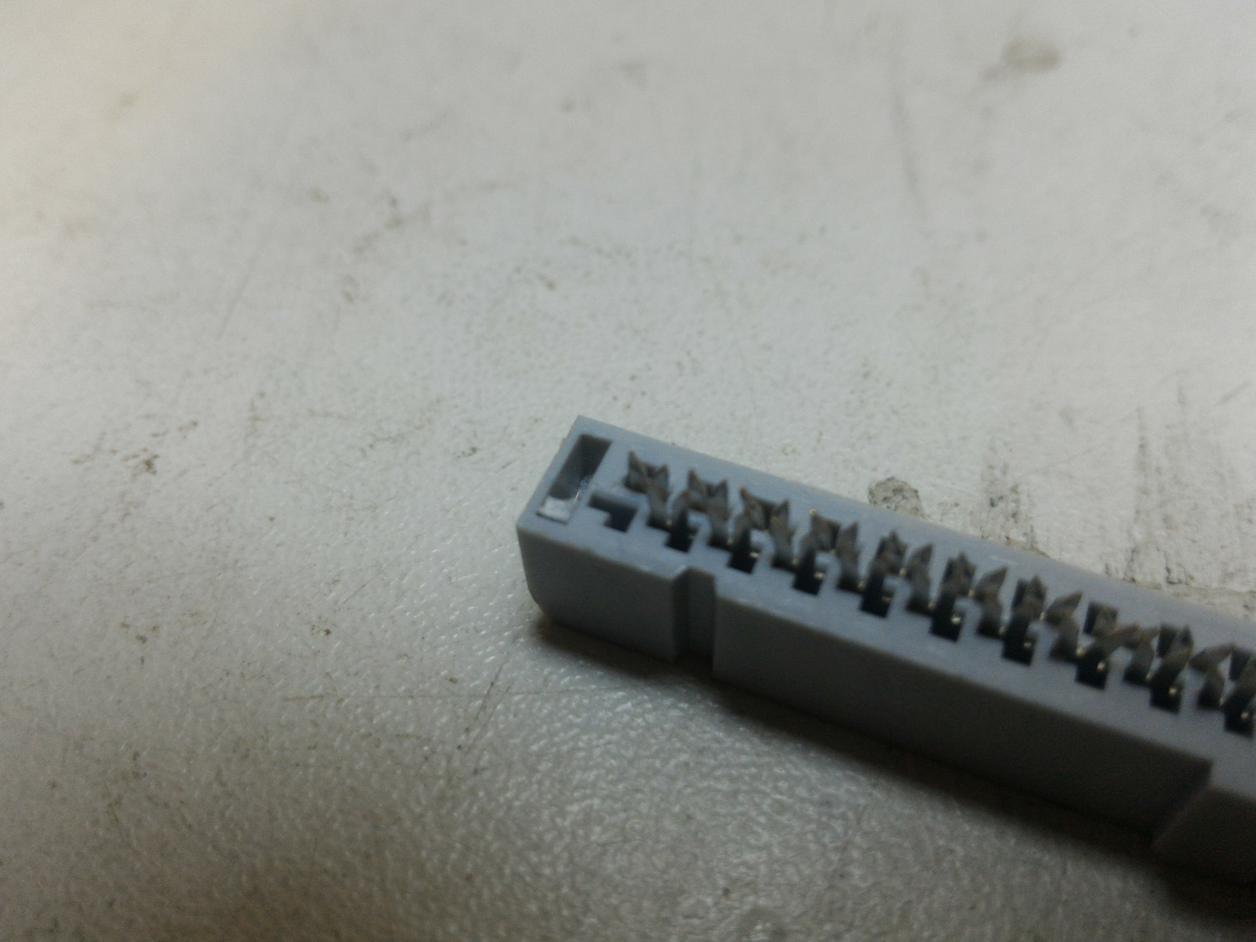
Once you have the clips off you need to remove the cable from the cables plug, Take your time with this because the pins will come out of the plug if you don’t. If some of the pins come out you can just straighten them up and reinserted them back into the plug. The springy/raised part of the pin goes into the right side of the “L” shaped slot like below with the spiky end facing up like the rest.

Once the cable has been removed, you need to cut the cable down. Measure from the very end of the remaining plug 108mm and mark a line. You can use scissors to cutting the cable.
Now here comes the hard part, Putting the plug back onto the now cut down cable. The easiest way I found to do this was to line up the cable with the end of the plug then slid the clip over the top of it. Make sure the cable is lined up right then place it onto something solid like the floor and start tapping it with a hammer. Dont go mad with the hammer at this point, Make sure the cable is still lined up with the end of the plug then start hitting it a little harder until the cable and clip are all down flat.
When your happy its flat like the unmodded end, You will need to test ALL the pins now, I used the continuity test on a multimeter and 2 jumper cables. Even tho the cable was down flat some of the connects might now work, Don’t panic. Remove the clip again by flicking it out and pushing down. The way the pins work is quite simple. They are like scissors, some wont quite cut into the cable. You will need to check that all the scissor pins are closed enough to cut into the cable. I used some pliers on the pins that weren’t connecting then retested the connections. You should have a solid connection now but if you don’t just give them another squeeze with the pliers. When you are satisfied with all the connections you need to reattached the clip.
Raspbian with touch screen
Setup
So now that you have retropie all set up how you like it you might want to try out different OS’s on your portable. I found the easiest way to do this is grab the latest Raspbian image and burn it to a sd card in your normal way. After you have let it boot up, You will need to get the screen working with these commands.
cd
curl -O https://raw.githubusercontent.com/adafruit/Raspberry-Pi-Installer-Scripts/master/pitft-fbcp.sh
sudo bash pitft-fbcp.sh
Audio
Reboot and you will have a working screen. remember to get rid of the screeching I found this forum post about changing the refresh rate of the screen helped to stop it. Search in the /boot/config.txt file for
dtoverlay=pitft22,rotate=270,speed=80000000,fps=60
and change the speed from 8000000 to 4800000 like so
dtoverlay=pitft22,rotate=270,speed=48000000,fps=60
Its been a long-standing complaint with raspberry pi in general that you have a hissing sound when you plug-in headphones or speaker. I found that if you add
disable_audio_dither=1
to /boot/config.txt it goes away.
Touch screen
To get the touch screen working you will need to grab the files from adafruits github. Put them on your RPI’s sd card and unzip them. cd into that directory and run this command
sudo ./adafruit-pitft-helper -t 28r
Just hit Y to both questions then reboot
you will probably notice that the screen is upside down to change that you will need to edit your /boot/config.txt file. search for this line
dtoverlay=pitft28-resistive,rotate=90,speed=32000000,fps=20
and change it
dtoverlay=pitft28-resistive,rotate=270,speed=32000000,fps=20
You will also notice that you touch input is also inverted. To fix this you will need to edit this file /etc/X11/xorg.conf.d/99-calibration.conf
All I did was change the order of the numbers on this line
Option "Calibration" "287 3739 3817 207"
To this order
Option "Calibration" "207 3817 3739 287"
The numbers might be different on your files but you get the idea, Reboot and you should have a fully functioning build of raspbian.
Videos
Walk through of the mods – https://youtu.be/hT_qm_UdnRI
Controller PCB with soft touch buttons – https://youtu.be/FAbdXo4BPaI

Leave a reply to Scott Cancel reply